INDEX
NEGATIVE NUMBERS - 2's Complement
This guide was originally developed as a learning reference for the Computer Architecture
and Organization course; however, the guide has evolved enough to serve as an
introduction to the most basic concepts of z80 assembly.
Throughout the guide we will deal with the basic elements of the operation of the z80 Zilog
chip that we are going to use (battery, memory, color, etc.); as well as the most basic
instructions and reference codes on which to base ourselves.
The objective of this guide is to serve as a base and reference in case of doubts throughout the development (as a beginner) of programs in this system.
If you want to go deeper, a section with links of interest will be added at the end of the
document.
Installing the z80 emulator/compiler (if you don't have one):
DeZog documentation(in case you have difficulties)
|
A |
F |
ACCUMULATOR |
FLAGS |
|
B |
C |
(DJNZ) |
- |
|
D |
E |
- |
- |
|
H |
L |
(DIR) |
(DIR) |
|
SP |
STACK POINTER |
||
|
PC |
PROGRAM COUNTER |
||
|
IX |
DIR |
||
|
IY |
DIR |
||
|
I |
INTERRUPT VECTORS (DI) |
||
|
R |
MEMORY REFRESH |
||
THEY CAN BE USED FOR THEIR SPECIFIC USE AND TO SAVE VALUES
ACCUMULATOR REGISTER TO OPERATE AND COMPARE
REGISTERS FOR INDIRECT ADDRESSING WITH OFFSET
WE WON’T BE USING THEM
THERE ARE OTHER REGISTERS FOR EACH DOUBLE REGISTER, BUT WE ARE NOT GOING TO USE THEM
Types of values in memory addresses (and when we will use them):
It should be noted that all these data types are valid for any operation, we simply
standardize what we will do with each one to avoid confusion.
Registers sizes:
Marked by a '
A' F' B' C' D' E' H' L'
They function as a second form of the register and serve to store registers whose value will be lost, without using the stack.
The EXX instruction changes BC, DE, and HL to BC' DE' HL'; although we will not use it.
The flags are bits that can be 0 or 1 and determine that a previous operation or comparison has given a particular result. On a practical level, we will use these comparisons as if they were aif().
arg1 > a Carry set
arg1 <= a Carry reset
arg1 == a Zero set
arg1 != a Zero reset
Comparisons and similar operations are always done on the accumulator register (A). A flag is set when it becomes 0 and reset when it becomes 1. If an operation does not cause the flag to become set then the flag will be reset.
|
|
Flag Zero |
Flag Carry |
Accumulator |
|
inc 255 |
Set |
Set |
1 |
|
dec a |
Set |
Set |
1 |
|
sub a |
Set |
Reset |
x |
|
cp a |
Set |
Reset |
x |
Dec and Inc don't trigger the carry flag even if we carry something.
|
jr |
jr z,addr1 |
jump if zero flag set |
|
jr nz,addr1 |
jump if zero flag reset |
|
|
jr c,addr1 |
jump if carry flag set |
|
|
jr nc,addr1 |
jump if carry flag reset |
|
|
ret |
ret (n)flag,addr1 |
ret if flag (re)set |
|
jp |
jp (n)flag,addr1 |
jp if flag (re)set |
|
call |
call (n)flag,addr1 |
call if flag (re)set |
|
ld A, 4 ;loads a number in A |
|
inc C ;does C = C + 1 |
|
dec C ;does C = C - 1 |
|
ld A, 4 ; loads 4 in A |
Esto también funciona con registros dobles
|
ld A, 4 ; loads 4 in A |
The logical operations are done bit by bit on the 8 bits of register A (Bit 0 of A with bit 0 of the operand, Bit 1 of A with Bit 1 of the operand, Bit 2 of A with Bit 2 of the operand... up to bit 7).
Performs the logical operation shown below on register A and the simple register entered:
|
AND |
||
|
A |
B |
Resultado |
|
0 |
0 |
0 |
|
0 |
1 |
0 |
|
1 |
0 |
0 |
|
1 |
1 |
1 |
|
and C ;does A = A AND C |
Performs the logical operation shown below on register A and the simple register entered:
|
OR |
||
|
A |
B |
Resultado |
|
0 |
0 |
0 |
|
0 |
1 |
1 |
|
1 |
0 |
1 |
|
1 |
1 |
1 |
|
or C ;does A = A OR C |
Performs the logical operation shown below on register A and the simple register entered:
|
XOR |
||
|
A |
B |
Resultado |
|
0 |
0 |
0 |
|
0 |
1 |
1 |
|
1 |
0 |
1 |
|
1 |
1 |
0 |
|
xor C ;hace A = A XOR C |
Name that is assigned to the memory address that contains the instruction after the label, except if the EQU directive exists. For example:
|
label_example: EQU 5 ;makes label_example value 5 |
In any other case:
|
label_example: ld C, 8 |
|
label_example: jp lable_example |
Define byte > 1 byte (8 bits) can be defined at an address indicated by a label. The memory address of all those entered after the first byte is equal to the address of the first byte plus its position:
1º Label address + 0
2º Label address + 1
3º Label address + 2
…
|
array: .db 1, 4, 7, 2, 252 ;for some compilers the dot can be omitted |
|
variable: .DEFB 0 |
Define word > 2 bytes (16 bits) can be defined at an address indicated by a label. The memory address of all those entered after the first byte is equal to the address of the first byte plus its position:
1º Label address + 0
2º Label address + 1
3º Label address + 2
|
array: .dw 1 2, 7 8, 134 2, 0 252 ;for some compilers the dot can be omitted |
|
array_de_2: .DEFW 0 0 |
Define space > A given number of bytes can be defined at an address indicated by a label. The memory address of all those entered after the first byte is equal to the address of the first byte plus its position:
1º Label address + 0
2º Label address + 1
3º Label address + 2
|
array_de_8_a_0: .ds 8, 0 ; this is equivalent to: 0, 0, 0, 0, 0, 0, 0, 0 ; for some compilers the dot can be omitted |
|
array_de_3_a_4: .DEFS 3, 4 ; this one would be: 4, 4, 4 |
The Stack Pointer (sp) always points to the last element stored on the stack. The stack grows by decrementing the memory location and values are removed by increasing the memory location.
The stack also stores double registers (16 bits); therefore, it increases or decreases 2 by 2.
We must also know that it is located inside of the RAM and, if we initialize SP in $0, we will have something like what is seen in the following table:
|
Memory Address |
Value |
|
$FFF8 |
$A38B |
|
$FFFA |
$EAFD |
|
sp > $FFFC |
04 | 05 |
|
$FFFE |
02 | 03 |
|
$0000 |
00 | 01 |
One of the important things to know is that when adding a new element to the stack, the pointer is first moved and then the value is added. Initializing the stack at $0000 makes it so that we never store anything in $0000, but instead to $FFFF and $FFFE and so on. We do this because the address $0000 is inside the ROM not the RAM.
In memory, from lowest to highest position, the R_right is saved and then the R_left:
It works the other way around:
It checks the state (set or reset) of a specific bit and modifies the Z flag; If the bit is 0, the Z flag is reset to 1 and vice versa.
Receives:
|
bit 1, C ;C = 0 1 0 0 1 0 1 1 |
Set state to a specific bit
Receives:
|
set 2, C ;nuevo C = 0 1 0 0 1 1 1 1 |
Reset state to a specific bit
Receives:
|
res 6, C ;nuevo C = 0 0 0 0 1 0 1 1 |
Address → $4000
Size = 192 rows x 32 columns = 6144 = $1800
Bitmaps (spriting)
Address → $5800
Size = 24 rows x 32 columns = 756 = $300
It's an isolated I/O port, on a device called a ULA, that handles the keyboard, border, and sound:
Address → $fe
We initialize the code and the stack at these positions, but it is remarkable that this is not necessary.
Code → (org $8000) → $8000
Stack Pointer → (sp 0) → $00
It checks the state (set or reset) of a specific bit to know the state of the flag it represents. These are:
|
F |
|||||||
|
Bit 7 |
Bit 6 |
Bit 5 |
Bit 4 |
Bit 3 |
Bit 2 |
Bit 1 |
Bit 0 |
|
S |
Z |
F5 |
H |
F3 |
P/V |
N |
C |
Where:
C (Carry) > > > Set if the result of an operation does not fit in a register.
Z (Zero) > > > Set if the result of an operation is 0
N (Subtract) > > > Set if the operation was a subtraction
S (Sign) > > > Set if the value of the complement to 2 in negative
P/V > > > If odd parity in logical operations (odd number of ones in a byte) or 2's
Complement Overflow in math operations (which means 2's Complement does not fit
in 1 register)
To call (only functional with jp and call) the flags that we have not seen previously we use:
For Sign > > > s
For Subtract > > > n
For Parity > > > pe > > > Set if Parity Even
> > > po > > > Set if Parity Odd
For % 0 0 0 0 1 1 0 1, if we rotate to the right:
Option 1:
% 1 0 0 0 0 1 1 0 > The original bit is moved
Option 2:
% 0 0 0 0 0 1 1 0 > The original bit becomes 0
If we rotate to the left:
Option 1:
% 0 0 0 1 1 0 1 1 > The original bit is kept
Option 2:
% 0 0 0 1 1 0 1 0 > The original bit becomes 0
SLA
|
sla 8_bit_register |
Rotate left and:
Bit 7 (the one that disappears) goes to the carry
flag Bit 0 (the new one) reset (it is set to 0)
SRA
|
sra 8_bit_register |
Rotate right and:
Bit 0 (the one that disappears) goes to the carry flag Bit
7 (the new one) reset (set to original value)
SRL
|
srl 8_bit_register |
Rotate the register to the right and:
Bit 0 (the one that disappears) goes to the carry flag
Bit 7 (the new one) reset (set to 0)
For % 0 0 0 0 1 1 0 1, if we rotate to the right:
% 1 0 0 0 0 1 1 0
If we rotate to the left:
% 0 0 0 1 1 0 1 0
Imagine the byte as a continuous strip (i.e. glued to a cylinder).
RL
|
rl 8_bit_register |
Rotate register left and:
Bit 7 (the one that disappears) is set in the carry flag
Bit 7 (the new one) is set to 0
RLA
RL for register A.
RLC
|
rlc 8_bit_register |
Rotate register left and:
Bit 7 goes to bit 0
Bit 0 goes to carry flag
For % 1 1 1 1 0 0 0 0, RLC would result in:
% 1 1 1 0 0 0 0 1 and the carry would be 1
RLCA
RLC for register A.
RR
|
rr 8_bit_register |
Rotate register right and:
Bit 7 (the new one) becomes the value that the carry flag had
Bit 0 (the one that disappears) is put into the carry
RRA
RR for register A.
RRC
|
rrc 8_bit_register |
Rotate record right and
El bit 0 goes to bit 7
El bit 0 goes to carry flag
RRCA
RRC for register A.
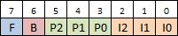
The colors in z80 are determined by the following graph, where the combination of 8 bits
generates the number that we must assign to the corresponding coordinates on the
screen to put a square of the color in that position.
Where:
F (Flash) determines the mode
>>> Set Paper and Ink colors flicker
>>> Reset shows the Ink color over the Paper color
B (Brightness) determines the brightness of the color
>>> Slear colors with set
>>> Dark colors with reset
P2 to P0 (Paper) determines the color of the
background (binary)
I2 to I0 (Ink) determines the main color (binary)
An example would be the color light red:
|
F |
B |
PAPER |
INK |
||||
|
0 |
1 |
0 |
1 |
0 |
0 |
0 |
0 |
Another example would be flashing between light yellow and green:
|
F |
B |
PAPER |
INK |
||||
|
1 |
1 |
1 |
0 |
0 |
1 |
1 |
0 |
Does the instructions shown below:
|
cp (HL) |
Does the instructions shown below:
|
ld (DE), (HL) |
Does LDI until BC is 0.
Does the instructions shown below:
|
ld (DE), (HL) |
Does LDD until BC is 0.
Stores in register A (or HL, for 16 bits) the result of subtracting the sum of the second operand and the value of the carry flag from register A (or HL, for 16 bits).
|
sbc A, 8_bit_register sbc HL, 16_bit_register |
Saves in register A (or HL, for 16 bits) the result of the addition of the second operand, register A (or HL, for 16 bits) and the value of the carry flag.
|
sbc A, 8_bit_register sbc HL, 16_bit_register |
In the representation of negative numbers in binary we use 2's complement. To do this, we take a number in binary and exchange the 1s for 0s and the 0s for 1s. In the following example we convert 5 to negative (251):
% 0000 0101 >> We swap >> % 1111 1010 +1
However, in z80 we don't stop there, the processor adds 256 (%1 0000 0000) to the number in question to store it as a negative.
You can load negatives directly with LD:
|
ld A, -10 ;however, it is more advisable to make negatives |
There are 2 ways to make negatives in z80:
Two's complement in z80 is done:
|
ld A, 5 ;in A there is now a 5, that is %00000101 |
To make the 5 negative, we reverse the 1s and 0s:
|
xor A ;we use the exclusive or to convert it to %11111010 ;another way: |
Then we add 1:
|
inc A ;now we have %11111011 |
Keyboard in Z80 works by checking bits from the memory addresses in the following table.
|
|
Bit |
||||
|
Puerto |
0 |
1 |
2 |
3 |
4 |
|
$FEFE |
Shift |
Z |
X |
C |
V |
|
$FDFE |
A |
S |
D |
F |
G |
|
$FBFE |
Q |
W |
E |
R |
T |
|
$F7FE |
1 |
2 |
3 |
4 |
5 |
|
$EFFE |
0 |
9 |
8 |
7 |
6 |
|
$DFFE |
P |
O |
I |
U |
Y |
|
$BFFE |
Enter |
L |
K |
J |
H |
|
$7FFE |
Space |
Sym |
M |
N |
B |
|
key: db. 0 ; Variable where to store the last key pressed check_keys:
|
1) Sum of the elements of an array of unknown size with end delimiter
(with value 255) that is returned by register A.
This sum cannot be greater than 201; if it is, return the nearest smaller sum.
Entry > in HL the variable
Departure > in To the sum
2) Check if the first and last elements of an array of unknown size
with an end delimiter (with value 255) are equal.
If they are, return through register A a number whose bit 4 is 1 and, if not, bit 4 is 0.
3) Combine 2 arrays of size 4 into one of 8 so that the elements of both
alternate.
Which means that the result will look like:
Arr1 : 1a, 1b, 1c, 1d
Arr2 : 2a, 2b, 2c, 2d
ArrR : 1a, 2a, 1b, 2b, 1c, 2c, 1d, 2d
4) Eliminate the elements of value 3 from the following array of size 12:
Example array: [0, 2, 0, 3, 1, 0, 1, 3, 0, 3, 2, 1]
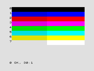
5) Paint the following array on the screen in an inverted way (it has the exact
necessary number of values):
label_display:
DEFS 32, $02, 32, $02, 32, $02, 32, $02, 32, $02, 32, $02, 32, $02, 32, $02, 32, $02, 32, $02, 32, $02, 32, $02
DEFS 32, $01, 32, $01, 32, $01, 32, $01, 32, $01, 32, $01, 32, $01
DEFS 32, $04, 32, $04, 32, $04
DEFS 32, $03, 32, $03
7) Given that you know the number of elements in the stack, invert the stack
8) Divide a number in Hundreds, Tens and Units
An example:
number: db 231
divided: db 2, 3, 1
9) Tic-Tac-Toe
Game in which we manage turns, 2 players (red and blue), board and a game over.
Knowing that 3*3 = 3+3+3 and that 6/3 = nº(3+3) = 2
Multiply
|
ld C, 2 |
Divide 8 bits / 8 bits (divisible by each other)
|
ld C, 0 ;C es nuestro contador |
Division 8 bits / 8 bits (with remainder)
|
; D divided by E sla D |
|
ld B, 2 ;a*2^(b-1) |
|
ld B, 2 ;a/2^(b-1) |
Stored in A, generated from register R
|
random_number: |
|
output "filename.bin" ;output file generated (for Sublime Text) |
|
funcName: push AF
;We return the function to where it was called (the next instruction after call) |
|
ld B,10 loop1: djnz loop1 ;B == 0?
;----------------------------------
ld C,10 loop2: inc C ld A,C cp 0 jr C, loop2 ;C <= 0?
;----------------------------------
ld D,0 loop3:
dec D ld A,D cp 10 jr nz, loop3 ;D != 10?
ld E,0 loop4: inc E cp 12 jr z, loopend4 ;E == 12? jr loop4 loopend4: |
|
;Code by professor Daniel León - UFV ;Function call ;function |
|
;Call function ;Function drawBorders:
|
Paints a box of color A at the X,Y coordinates (1..32, 1..24). Receive X,Y and color
coordinates with registers B,C and A respectively.
This function determines the address with the formula: Address = $5800+32*Y+X.
|
;Code by professor Daniel León - UFV ;Call function ;Function cuadroXYC: |
z80 Guide by Matt Heffernan - Youtube Playlist
z80 game development by James Malcolm - Website
z80 Heaven - Wiki
z80 Zilog - User Manual
Multiplatform z80 Assembly Programming by ChibiAkumas - Website
Zilog Z80A Technical Information by WorldOfSpectrum - Website
Sprites in ZX Spectrum - Website
Última actualización: 10 / 2022